Connection of plasma cutter – Voltage divider must be connected before the pilot arc.
Plasma cutter/CNC control separated by Optokoppler.
12V operating voltage from CNC control
Max 5V input from voltage divider, if using voltage divider from PlasmaCutter
Adjustable Plasma Voltage: 110V-150V via button
LCD I2C display (5V)
3 LEDs – 2 Status indicators: THCUP, THCDOWN
Menu: Calibration, PlasmaSoll, ResetToDefault, Active State LOW/HIGH,
Simple Hardware Test, Disable LCD Update during cut, About THC Controller
3 buttons: SELECT, UP, DOWN (for menu navigation)
PCB 2xSSR OMRON G3VM-61 relays not assampled (no function in software yet)
Programmable via ISP AVRDUDE (code in Arduino IDE, partially low-level)
⚠️ Safety Warning and Disclaimer
Warning: This tool is used for installation at the user’s own risk. High voltage (>50V) can be lethal. Ensure safe handling.
Disclaimer: Any liability for damages, particularly personal injury or property damage, arising from improper use of this tool is excluded to the extent legally permitted. The user assumes full responsibility for the safe and proper use of this tool during installation and operation.
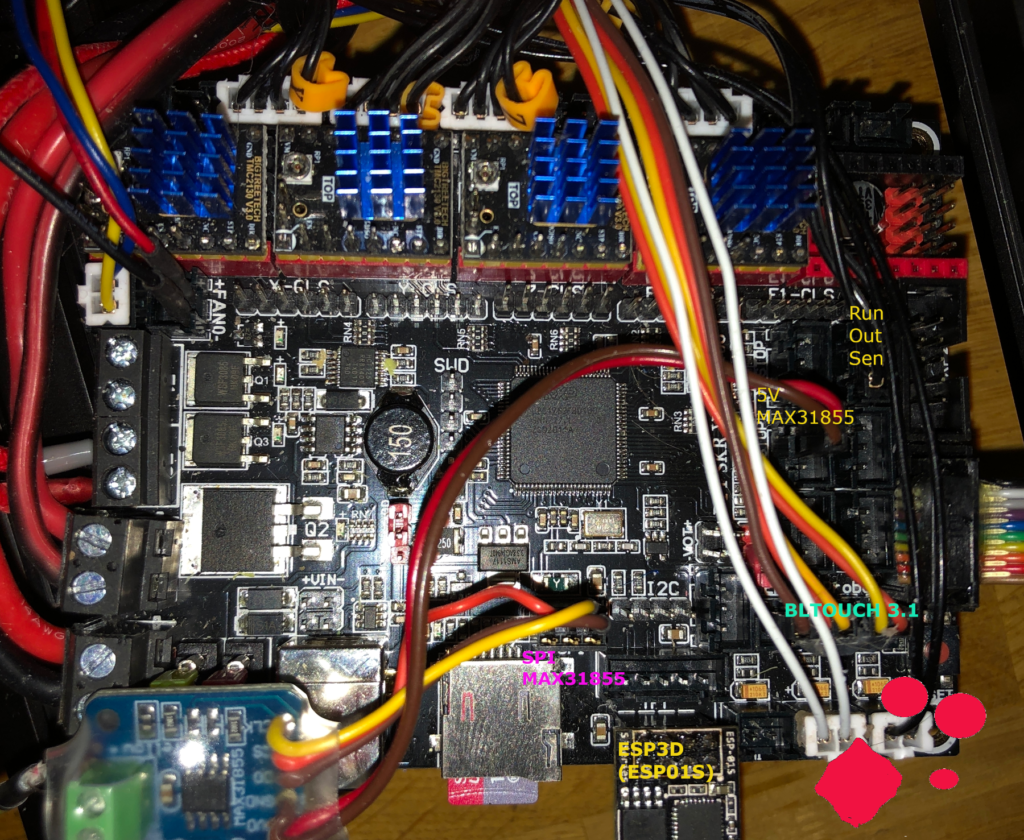
🛠️ Connection to CNC Plasma
Connection Pins THC Controller
Connection setup for CNC Plasma with THC Controller.Continue reading
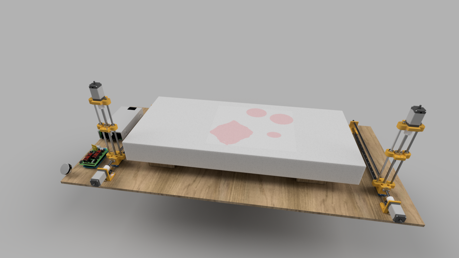
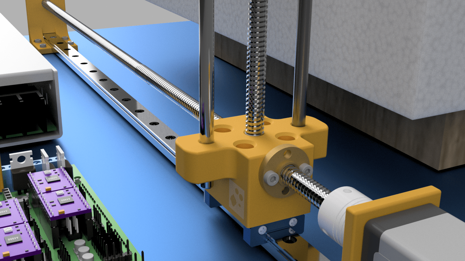
2x Linear Guide Size: MGN12H 500mm or the size you like (X-Size)
16x Zylinderkopf-Schrauben M2.5X10 or M2.5X6 to mount NEMA11
16x Zylinderkopf-Schrauben M3x12
Washers (Unterlagsscheiben) for M3 and M2.5 –> Recommended !!
1x NiCr Wire to cut Styro
1x Retractable Pull Key Ring –> to span NiCr Wire
4x Steel Round 6mm size depends on your Y-size
1x Wooden Plate to mount the hole stuff
10 x M3 Screws to mount Linear Guide to Wood plate –> Size is your choice
10 x M3 Stainless Steel Flat Head Threaded Rivet Insert Nutsert Cap Rivet Nut –> You can drill wooden plate and insert dem from below to fix Linear Guide
Access to a simple turning maschine to adapt the T8-Spindle that it will fit in Ball Bearing and StepperMotor Coupler
I recommend you to have some drills around to cleanup the holes after doing the 3d-Print – Specialy for the Ball Berings, Linear Bearings and the Y-Axis – You need 6.0mm, 8.0mm. 12.0mm –> Recommended that the everything fits well !! – To cleanup the through-hole for screws and T8 Nut –> 3.2mm and 10.5mm –> Optional
!! -> Ordered the the most things on Aliexpress if you don’t have local store available
IMPORTANT check that you have comment out (//) all below listed Parameters –> This ones are essential that BLTOUCH will work with BTT 1.4 Turbo. The BOLD Marked Parameters and Parametes are very important
–> Modifiy this Line –> Remove “HAS_GRAPHICAL_LCD &&” //#if HAS_GRAPHICAL_LCD && EITHER(SDSUPPORT, LCD_SET_PROGRESS_MANUALLY) #if EITHER(SDSUPPORT, LCD_SET_PROGRESS_MANUALLY) //2021-01-17 MROE to Display Remaining time with Ender3Pro LCD
#define PRINT_PROGRESS_SHOW_DECIMALS // MROE 2020-05-23 Show progress with decimal digits #define SHOW_REMAINING_TIME // MROE 2020-05-23 Display estimated time to completion #define USE_M73_REMAINING_TIME // MROE 2020-05-23 Use remaining time from M73 command instead of estimation #define ROTATE_PROGRESS_DISPLAY // MROE 2020-05-23 Display (P)rogress, (E)lapsed, and (R)emaining time #define SCROLL_LONG_FILENAMES // MROE 2020-05-23 #define SDCARD_CONNECTION ONBOARD // MROE 2020-05-23 BTT SKR V1.4 TURBO Use on Board SDCard #define X_CURRENT 650 // MROE 2020-05-14 (mA) RMS current. Multiply by 1.414 for peak current. #define Y_CURRENT 650 // MROE 2020-05-14 #define Z_CURRENT 660 // MROE 2020-07-12 because of heavy z-axis #define E0_CURRENT 650 // MROE 2020-05-14 #define TMC_USE_SW_SPI // MROE 2020-07-12 SPI TMC2130 muss aktiv sein #define CHOPPER_TIMING CHOPPER_DEFAULT_24V // 2020-10-16 MROE Ender3 Pro has 24V Power #define MONITOR_DRIVER_STATUS // MROE 2020-05-14 #define HYBRID_THRESHOLD //MROE 2020-05-16 #define SENSORLESS_HOMING // MROE 2020-05-14 StallGuard capable drivers only #define X_STALL_SENSITIVITY 10 // MROE 2020-05-14 Default 8 #define Y_STALL_SENSITIVITY 10 // MROE 2020-05-14 Default 8 #define TMC_DEBUG // MROE 2020-05-14 #define CANCEL_OBJECTS // MROE 2020-05-23 //#define ESP3D_WIFISUPPORT // MROE 2020-07-19 ESP3D Library WiFi management (https://github.com/luc-github/ESP3DLib) #define LPC_PINCFG_UART3_P4_28 // MROE 2020-10-09 from Marlin 2.0.7 define UART Port for Wifi ESP3D –> HardwareSerial.h SKR 1.4 Turbo #define WEBSUPPORT // MROE 2020-07-19 Start a webserver (which may include auto-discovery) #define OTASUPPORT // MROE 2020-07-19 Support over-the-air firmware updates
configuration.h
#define SHOW_CUSTOM_BOOTSCREEN // MROE 2020-05-15 #define CUSTOM_BOOTSCREEN_TIMEOUT 4000 // MROE 2020-05-15 #define CUSTOM_BOOTSCREEN_BMPWIDTH 128 // MROE 2020-05-15 #define CUSTOM_BOOTSCREEN_BMPHEIGHT 64 // MROE 2020-05-15 #define CUSTOM_BOOTSCREEN_INVERTED // MROE 2020-05-15 #define SERIAL_PORT 3 // MROE 2020-05-14 -1 –> https://github.com/bigtreetech/BIGTREETECH-SKR-V1.3/issues/221 #define SERIAL_PORT_2 -1 // MROE 2020-07-19 Fix EP3D –> /.platformio/packages/framework-arduino-lpc176x/cores/arduino/HardwareSerial.h #define BAUDRATE 115200 // MROE 2020-05-15 #define TEMP_SENSOR_0 -3 // 2020-10-16 MROE active Thermocouple MAX31855 for Extruder0 #define PID_EDIT_MENU // MROE 2020-07-18 Add PID editing to the “Advanced Settings” menu. (~700 bytes of PROGMEM) #define PID_AUTOTUNE_MENU // MROE 2020-07-18 Add PID auto-tuning to the “Advanced Settings” menu. (~250 bytes of PROGMEM) #define PIDTEMPBED //MROE 2020-05-23 #define EXTRUDE_MAXLENGTH 400 // MROE 2020-05-23 Ender3 Pro //#define ENDSTOPPULLUP_ZMIN // MROE 2020-05-30 BLTOUCH V3.1 //#define ENDSTOPPULLUP_ZMIN_PROBE // MROE 2020-05-30 BLTOUCH V3.1 #define X_MIN_ENDSTOP_INVERTING true // MROE 2020-05-14 Sensorelss Homing TMC2013 Set to true to invert the logic of the endstop. #define Y_MIN_ENDSTOP_INVERTING true // MROE 2020-05-14 Sensorelss Homing TMC2013 Set to true to invert the logic of the endstop. #define Z_MIN_PROBE_ENDSTOP_INVERTING true // MROE 2020-07-16 Set to true to invert the logic of the probe. #define X_DRIVER_TYPE TMC2130 //MROE 2020-05-14 #define Y_DRIVER_TYPE TMC2130 //MROE 2020-05-14 #define Z_DRIVER_TYPE TMC2130 //MROE 2020-05-14 #define E0_DRIVER_TYPE TMC2130 //MROE 2020-05-14 //#define ENDSTOP_NOISE_THRESHOLD 2 // 2020-07-27 MROE in compatible with sensorless homing #define DEFAULT_AXIS_STEPS_PER_UNIT { 80, 80, 400, 93 } // MROE 2020-05-23 Ender3 Pro #define DEFAULT_MAX_FEEDRATE { 500, 500, 20, 60 } // MROE 2020-05-23 Ender3 Pro #define DEFAULT_MAX_ACCELERATION { 3000, 3000, 25, 10000 } // MROE 2020-07-12 Acceleration Z-Axis reduced because of heavy axiy #define DEFAULT_ACCELERATION 500 // MROE 2020-05-23 Ender3 Pro #define DEFAULT_RETRACT_ACCELERATION 500 // MROE 2020-05-23 Ender3 Pro #define DEFAULT_TRAVEL_ACCELERATION 500 // MROE 2020-05-23 Ender3 Pro #define S_CURVE_ACCELERATION // MROE 2020-05-30 //#define Z_MIN_PROBE_USES_Z_MIN_ENDSTOP_PIN // not needed MROE 2020-07-16 BLTOUCH V3.1 when BL Touch usese Z-MIN Enndstop pin #define Z_MIN_PROBE_PIN P0_10 // MROE 2020-07-16 BTOUCH Servo Pin BTT 1.4 Turbo P0_10 #define BLTOUCH // MROE 2020-05-30 Activated BLTOUC V3.1 #define USE_PROBE_FOR_Z_HOMING // MROE 2020-07-16 //#define SENSORLESS_PROBING // Because Screw Ender3 MROE 2020-07-16 BLTOUCH needs TMC2130 #define NOZZLE_TO_PROBE_OFFSET { -41, -10, -1.04 } // MROE 2020-05-30 –> Values from https://www.thingiverse.com/thing:3003725 #define XY_PROBE_SPEED 5000 // MROE 2020-05-30 #define MULTIPLE_PROBING 2 //MROE 2020-07-18 //#define Z_AFTER_PROBING 5 // MROE 2020-07-18 Z position after probing is done #define Z_MIN_PROBE_REPEATABILITY_TEST // 2020-07-27 MROE #define INVERT_X_DIR true // MROE 2029-05-30 Ender3 Pro #define INVERT_Y_DIR true // MROE 2029-05-30 Ender3 Pro #define INVERT_E0_DIR true // MROE 2029-05-30 Ender3 Pro #define X_BED_SIZE 235 // MROE 2020-05-23 Ender3 Pro #define Y_BED_SIZE 235 // MROE 2020-05-23 Ender3 Pro #define Z_MAX_POS 250 // MROE 2020-05-23 Ender3 Pro #define SOFT_ENDSTOPS_MENU_ITEM // MROE 2020-07-18 Enable/Disable software endstops from the LCD #define AUTO_BED_LEVELING_BILINEAR // MROE 2020-05-30 Activate Auto Bedleveling #define GRID_MAX_POINTS_X 5 // MROE 2020-05-30 #define LEVEL_CENTER_TOO // 2020-07-27 MROE Move to the center after the last corner #define Z_SAFE_HOMING // MROE 2020-07-11 #define EEPROM_SETTINGS // MROE 2020-05-23 Persistent storage with M500 and M501 #define NOZZLE_PARK_FEATURE //MROE 2020-07-11 #define SDSUPPORT // MROE 2020-05-30 #define INDIVIDUAL_AXIS_HOMING_MENU //MROE 2020-07-18 #define NUM_SERVOS 1 // MROE 2020-05-30 BLTOUCH V3.1 Servo
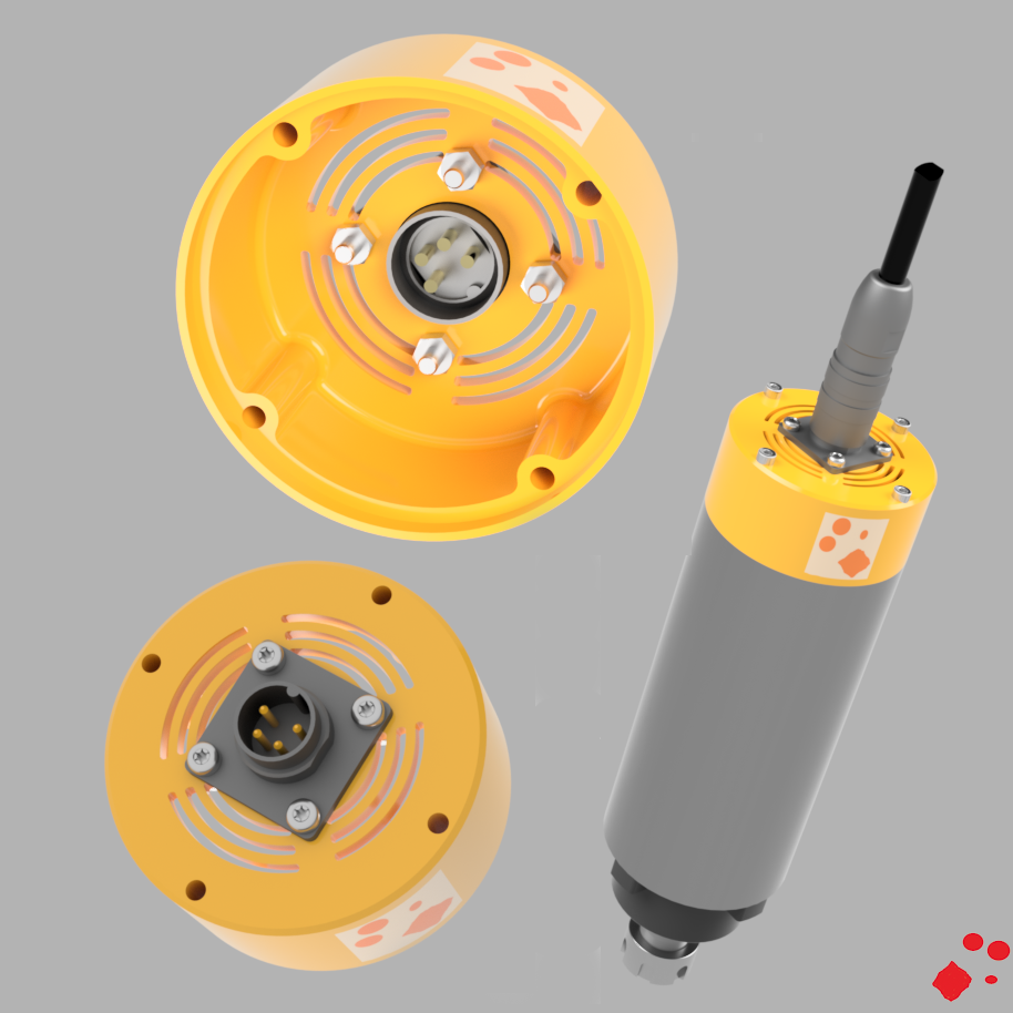
I adapted China air cooled spindle with GND to be save when Spindle get’s an electrical damage. (Did for 800W and 1.5kW spindle from different sellers) –> Spindel outer diameter 65mm
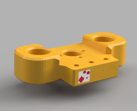
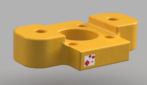
Print orange part with 3d Printer –> File as GCode attached to this post. –> ABS Fillament used 10,35m 1.75mm –> It tooks me about 4.5 hours to print on my 3d printer
Should work for all air cooled China Spindle
Needed Parts:
1 x Lumberg LUM 0318-04
1 x Lumberg LUM 0322-04
3m x Ölflex 110 CY 4G 0.75mm^2
3 x M3 x 45mm
4 x M3 x 10mm
1 x M3 x 8mm
4 x Mutter M3
1 x Kabelschuh M3 –> Connection Ground (GND)
I used only three M3 x45 screws because the 4th thread is used to connect grounding to the spindel. Remove the distance holder to get space for the screw to connect GND to spindle
Plug connection:
PIN 1 –> Cable 3
PIN 2 –> Cable 2
PIN 3 –> Cable 1
PIN 4 –> GND
If spindle turns in wrong direction after connecting to inverter, exchange cable (ex. PIN1 and PIN2) –> Now it should turn in correct direction.
Hello all,
Currently I’m going to adapt my Arduino 9 Shield Board for securing my CNC Maschines against unallowed access.
Code has been used together with an older Arduino Nano Shield.
Following fuctions are implemented:
set master iButton with first use
delete all allowed iButtons except master
add new iButtons
1-Wire Temperatur
show hours since switch on
list all Hex-ID’s of allowed iButtons during startup
show status with IButton Reader (green (ON) or red led(OFF))
switch relais on/off if valid iButton as been touched on iButton Reader
emergency Button push controll (switch off releais)
display DS1307 (RTC) time
correct time with spare Arduino Nano V3 durring upload –> new time will be programming time
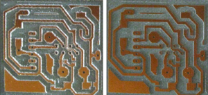
It’s very important to have a clamp with a run out (circulation) as small as possible. See picture bellow (left I used a bad clamp and on the right a good one). With same mill
PCB on the right has been milled with about double feed rate Used tool 60° VHM Mill
Generation Options Feed rate X,Y: 500mm/s Spot drill holes: -0.55mm Minimum: 0.0254mm Maximum: 1.6mm Step Size: 0.127mm Maschine Z Down: -0.2mm Tool Dia: 0.23094mm –> dependend on ZDown and Mill° (60° and -0.2) –> Calculated –> (tan(30°)*2)*ZDown= 0.23094mm
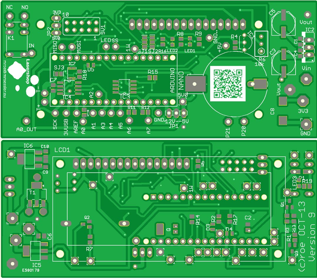
Created new Arduino Nano Shield Version 9 Arduino Nano Shield which supporting all current Maxim Thermocouple Chips – MAX31850 1-wire – MAX6675 I2C – MAX31855 I2C PCB is prepaired also for following option: – DS1307Z Realtime Clock – 1-Wire devices (ex. DS18S20,../blog../blog) – 3.3V voltage regulator LM1117MPX-3.3V – 5V oder 12V voltage regulatorr LM2937IMP oder LM340 – Relais G5V1 5V oder 12V You can connect a 2×16 LCD Display: – HD44780 LCD 2X16
Don’t care if they need 3.3V or 5V or if thermocouple has to be grounded, everything is implemented to get them running with different assembly options
If you are scared about soldering the MAX31850. It’s really simple if you do it in the following way:
1. Clean the PCB 2. Put some solder on the MAX31850 pads, there should be some smale solder balls on the pads 3. Place carefully the MAX31850 on the PCB, take care align it correctly to the solder pads on the PCB 4. Take an air rework station to fix it on the PCB, the solder has only to fix the chip. It will be soldered in the next step 5. Put a little flux paste beside the MAX31850 chip 6. Solder it with a soldering iron on the PCB 7. You can see that it’s good soldered when solder is covering the hole pad on the PCB


