

📄 PDF Documentation
Function
-
- Voltage divider: 1:53 (optional)
- Connection of plasma cutter – Voltage divider must be connected before the pilot arc.
- Plasma cutter/CNC control separated by Optokoppler.
- 12V operating voltage from CNC control
- Max 5V input from voltage divider, if using voltage divider from PlasmaCutter
- Adjustable Plasma Voltage: 110V-150V via button
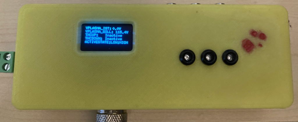
- LCD I2C display (5V)
- 3 LEDs – 2 Status indicators: THCUP, THCDOWN
- Menu: Calibration, PlasmaSoll, ResetToDefault, Active State LOW/HIGH,
Simple Hardware Test, Disable LCD Update during cut, About THC Controller
- 3 buttons: SELECT, UP, DOWN (for menu navigation)
- PCB 2xSSR OMRON G3VM-61 relays not assampled (no function in software yet)
- Programmable via ISP AVRDUDE (code in Arduino IDE, partially low-level)
⚠️ Safety Warning and Disclaimer
Warning: This tool is used for installation at the user’s own risk. High voltage (>50V) can be lethal. Ensure safe handling.
Disclaimer: Any liability for damages, particularly personal injury or property damage, arising from improper use of this tool is excluded to the extent legally permitted. The user assumes full responsibility for the safe and proper use of this tool during installation and operation.
🛠️ Connection to CNC Plasma
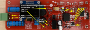
Connection Pins THC Controller

Connection setup for CNC Plasma with THC Controller.
Hardware Changes V3
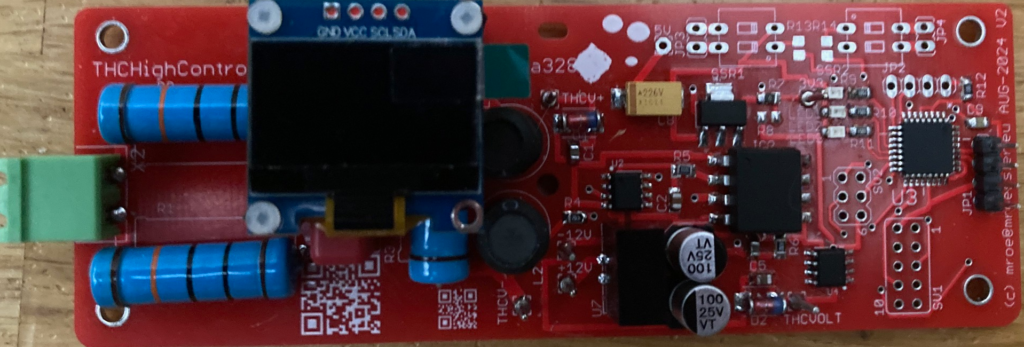
- SV2: Default ISP Programming Port for Atmega 328p
- SV1: Ports from Atmega328p V3
- P1:LED2
- P2:GND
- P3:THCVOLT
- P4:12VOUT
- P5:THCDOWN
- P6:THCUP
- P7:LED1
- P8:5VOUT
- P9:NC
- P10:LED3
- R8: Not anymore equipped
- R7: 0R because 3V3 not be used for I2C LCD
- JP1: I2C LCD 5V
- JP2: Button 3Stk
Connections Required
- +12V Connection: Connect +12V to the center of the board (from CNC Board).
- -12V Connection: Connect -12V to the center of the board (from CNC Board).
- THCUP/THCDOWN Connections: Connect to SV1, with PIN5 for THCDOWN and PIN6 for THCUP.
- JP1 to I2C-LCD: When using a DuPont connector, cross the cables on the left and right sides of the plug.
- SDA/SDL and 5V/GND Pin Adjustment: Carefully use a needle or small screwdriver to lift the pin blockers. Once lifted, you can pull out the pins to reposition if necessary.
- JP2 to Buttons: Connect to BUTTON_SELECT, BUTTON_UP, BUTTON_DOWN, and GND.
- Using a Custom Voltage Divider (“Spannungsteiler”): If using your own voltage divider, connect THCV- and THCV+ correctly. Ensure that the input does not exceed 5V. Lower input is acceptable, as the voltage divider can be calibrated.
Tip: Use schielded Cable to connect THC Controller to CNCPlasma (Use Ground CNC Plasma). If you have troubles with HF issues from PlasmaCutter LowPass Filter could solve your issues.
You need Capacitor and Resistor. –> Check Google for RC Values 100R and 3uF CutOff Freqency 500Hz could be ok.
Note: If you use the supplied Spannungsteiler from the PCB, connect PlasmaCutter to MTSBA2 (PIN1(+), PIN2(-)). Important: Take care that you use a connection where not the Voltage for PilotLichtbogen is available. In general inside of the PlasmaCutter before the coil for generating the PlasmaLichtbogen.
Programming Instructions
- SV2: Default ISP Programming Port for Atmega 328p
- Download: avrdude-6.4-mingw32.zip
- Adapt -P -c Parameter if you have other Programmer
- Fuse Settings:
- avrdude.exe -v -p atmega328p -c avrispv2 -P usb -U lfuse:w:0xe2:m (Internal Clock)
- avrdude.exe -v -p atmega328p -c avrispv2 -P usb -U hfuse:w:0xD1:m (Flash EraseEEPROM OFF)
- Program hex Settings:
- avrdude.exe -v -p atmega328p -c avrispv2 -P usb -U flash:w:thc1.02.hex:i
- Use the internal clock of Atmega 328p. (8Mhz)
Hier die Infos zum Update (von Discord):
von LittleWulf
Anleitung für Arduino Nano ISP Programmer
Link Bau Arduino Nano ISP Programmer
Treiber Installation
- Benötigte Komponenten: Sie benötigen einen Arduino Nano und einen 10µF-Elektrolytkondensator für die minimale Konfiguration.
- Programmierung ohne externe Spannungsquelle: Verwenden Sie die 5V-Spannung direkt vom Arduino Nano (PROG mit 5V vom Nano).
- Empfohlene Konfiguration: Ich habe mein eigenes Setup gebaut, das zuverlässig funktioniert. Hier sind die Details:
- Arduino Nano und 15µF-Kondensator: Löten Sie den Kondensator erst nach dem Programmieren des Nano ein; ein vorheriges Einlöten verhindert die Programmierung
- Einfaches Setup: Dies ist ein unkomplizierter und effektiver Ansatz für das Programmieren.
Kommandozeile für die Programmierung:
avrdude.exe -v -b 19200 -p m328p -c stk500v1 -P com3 -U flash:w:thc1.02.hex:i -F

Arduino IDE Compile Instructions
- Add following Board URL in Board Manager:

Firmware Downloads
Firmware thc1.01.hex 2024-10-24 (Initial)
Firmware thc1.02.hex 2024-11-27 (Add Display CalibrationValue, Reduced min. PlasmaSoll Voltage to 70V)
⚠️ Hinweis: Die heruntergeladenen Firmware-Dateien müssen möglicherweise umbenannt werden von .txt zu .hex.
Wichtige Info:
Falls kein ISP Programmer vorhanden ist, kontaktiert mich per
thccontroller”at”mroessler.eu
Neu-Flashen dauert nur 20 Sekunden.
